
There PCB quality is best in market, now I always go with PCB for my project and JLCPCB.COM is my trusted Like breadboard or Zero PCB earlier I also was in the same boat, I hesitate to try custom PCB my belief was they are much expensive.īut then I came to know about JLCPCB.COM and I was totally surprised how low price PCB's are they offering Yes PCB are the heart of the electronics based project usually we hesitate to try custom PCB and opt to homemade solutions More information about the L298N IC is found on its datasheet:īefore moving fuurther I would like to tell you something about PCB This means you can power high voltage motors while controlling them with microcontrollers. The most notable feature here is its high power supply although its input pins follow lower voltage levels. The diagram above shows an example diagram for using the L298N to drive one DC motor. To drive the motor counter clockwise, the pin Input 1 is low while the pin Input 2 is high. To drive a motor to a direction, say, clockwise, the pin Input 1 must be high while the pin Input 2 must be low. The Enable A pin must be high to turn on the motor. For example, if a motor is using channel A, its terminals must be connected to pins Out 1 and Out 2. This IC drives two motors through two channels, A and B. It comes in two IC packages: MultiWatt15 and PowerSO20. The L298N is an integrated circuit that follows the H-bridge concept. This is very significant especially when using an Arduino board where the 5V power source is simply not enough for two DC motors. The other benefit of using an H-bridge is that you can provide a separate power supply to the motors. On the other hand, when S2 and S3 are on, the right motor terminal is more positive than the left motor terminal, making the motor rotate in the other direction. When S1 and S4 are on, the left motor terminal is more positive than the right terminal, and the motor rotates in a certain direction. Here, the motor rotates in the direction dictated by the switches. The L298N motor controller follows the H-bridge configuration, which is handy when controlling the direction of rotation of a DC motor. This is where the L298N motor controller comes in. Obviously, you can’t drive loads that require much more current like a motor. There’s no problem there because the 20 mA or so current from the pins is enough. The archived DRI0002 Datasheet file may be downloaded here without warranties.You can drive a LED on or off using a microcontroller like Arduino or PIC.
L298n motor driver datasheet software#
Notice: we do not provide any warranties that information, datasheets, application notes, circuit diagrams, or software stored on this website are up-to-date or error free. # Description // # The sketch for using the motor driver L298N // # Run with the PWM mode # Product name L298N motor driver module DF-MD v1.3
L298n motor driver datasheet how to#
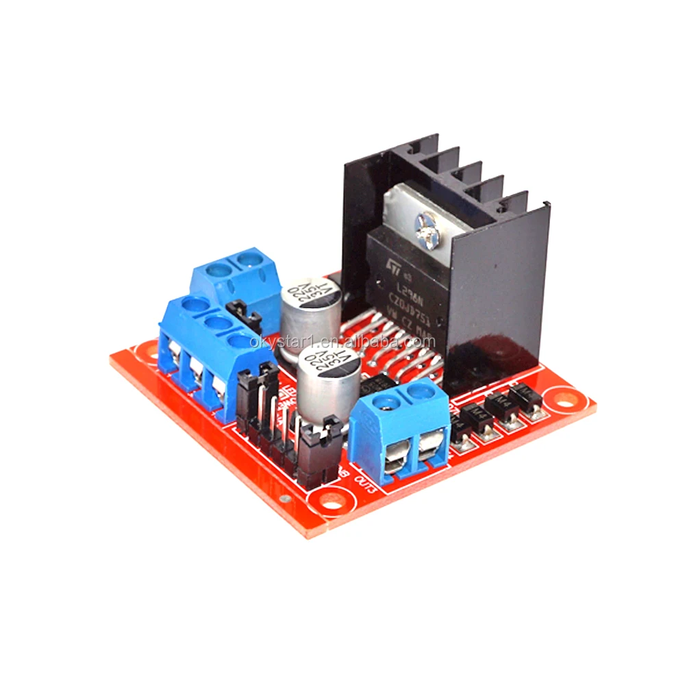
This tutorial shows you how to use l298N motor drive shield to drive two DC motors.

M1 = 1,the motor rotates in back direction. Eg M1 = 0,the motor rotates in forward direction. If motor power supply is more than 12V, dont't short jumper!Į1,E2 Motor Enable Pin(PWM M1,M2 Motor Signal Pin. If motor power supply is less than can set jumper shorted. When jumper is shorted, logic power supply voltage is the same as the motor power supply. VD Power Supply 6.5V~12V VS Motor Power Supply GND The common ground of Logic Power Supply and Motor Supply PWM Power LED Motor Status LED Motors work normally, thus the lED will light up. The terminals are used to connected to the motors, which labeled "+" and "-" representing motor polarity. Drive Type Dual high-power H-bridge driver.Operating temperature -25 degree Celsius ~ +130 degree Celsius.Maximum power dissipation 25W T = 75 degree Celsius.Drive part of the operating current Io 2A.The logical part of the work current Iss 36mA.Driven part of the input voltage Vs ~ 46V.The logic part of the input voltage 6 ~ 12V.The driver uses a broad-brush design to reduce wire resistance. 5 Tutorial Connection Diagram Sample Codeĭiodes for protection.Motor Terminal LED Power Supply Switching Jumper Motor Control Pins MD1.3 2A Dual Motor Controller SKU DRI0002 MD1.3 2A Dual Motor Controller SKU DRI0002 Part


 0 kommentar(er)
